When an EC-C inverter is used to control a generator, driven e.g. by a diesel or gasoline internal combustion engine (ICE), it is usually desirable to have an active torque limitation according to the engine RPM. This prevents stalling the engine, and allows raising the engine RPM in case more power output is needed, without externally controlling the inverter and it's torque limits.
The EC-C motor control application includes such function for limiting the generated torque as a function of the motor rotational speed. This function, called ICE controller (or icecon), is parametrized via defining a multipoint curve of speed-torque setpoints.
By defining the setpoints based on the ICE speed-torque curve, the need for external control of the inverter and ICE can be limited to starting, stopping and monitoring only. Also, fuel economy can be improved by defining the curve to produce power at optimally efficient ICE speeds.
Setting up the ICE controller
The ICE controller curve is defined by ten points of speed and corresponding torque values at those speeds. These values are located in parameter group icecon (10301). Values between the setpoints are interpolated with a linear curve between the points, and values below the lowest speed and above the highest speed will have the same torque limit as the lowest and highest setpoints, respectively.
Note that the curve should be set in such a way that the combustion engine has some headroom (available power) for accelerating after the limitation. As a rough estimate, the icecon curve should be set to approx. 75% of the maximum motor torque in the RPM range where the engine needs to accelerate.
An example icecon configuration and the resulting limitation is shown in figure 1 below. The inverter limits the available generating torque*, and thus power, using the set curve according to the actual motor speed, without lugging the ICE.
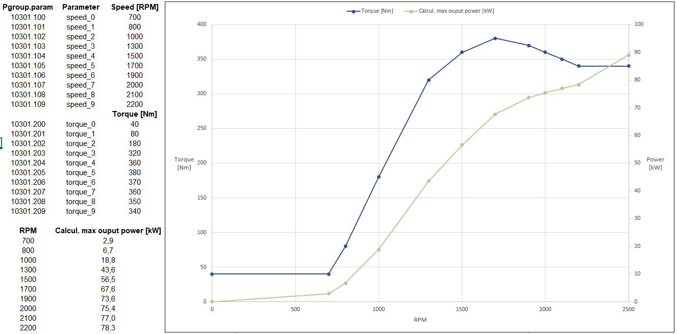
Figure 1. Example of the torque and power limitation which results from the icecon curve.
After configuring the speed-torque curve according to the installed engine and its capabilities, the ICE controller can be enabled by setting the parameter limits.b_ice_torque_limit_ena (10202.110) to TRUE. After this, the inverter will automatically limit the generating torque according to the ICE controller curve.
*Generating torque refers to torque which has opposite sign than the speed estimate of the inverter, and results in power taken out from the motor and transferred into the DC-link of the inverter.
Engine RPM reference calculation
In addition to the torque limitation according to motor RPM, the ICE controller also provides another useful function for generator control: automatic ICE RPM reference calculation. When this feature is enabled, the inverter will calculate the required RPM of the ICE according to the current DC-link power consumption, and sends this calculated RPM via CAN bus to the system controller or ICE control unit. This allows to automatically control the ICE RPM even without any external referencing or control. This feature is only available in devices using J1939 CAN protocol.
The CAN message for the calculated speed reference can be configured in parameter group engine_control. Available preconfigured message configurations for certain specific diesel engines can be selected from the engine_type selection. If a suitable engine is not listed, a generic speed reference message can be used by selecting the "PLC engine controller" and configuring a suitable PGN and transmission time for the message with the tsc1_pgn (50200.111) and tsc1_transmission_rate (50200.110) parameters. After configuring the message, the RPM reference calculation and transmitting via CAN bus can be enabled by setting parameter icecon.b_enable_ice_speed_ref_calc (10301.1) to TRUE.