The EC-C1200 inverter has freewheeling diodes which allow current to flow from AC side to DC side. An overcurrent or too high voltage over the IGBT diodes can cause severe damage to the diodes and thus result in a device failure.
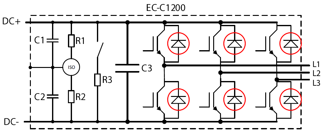
Figure 1. Electrical circuit diagram of EC-C1200 inverter. Freewheeling diodes marked with red circles.
Measuring freewheeling diodes
Any basic multimeter with diode measurement option can be used. Remember to use the diode measurement option, not resistance measurement.
Table 1. The principle of the measurement.
|
Diode (T = Top, B = Bottom) |
Multimeter negative probe |
Multimeter positive probe |
|
L1T |
DC+ |
L1 |
|
L2T |
DC+ |
L2 |
|
L3T |
DC+ |
L3 |
|
L1B |
L1 |
DC- |
|
L2B |
L2 |
DC- |
|
L3B |
L3 |
DC- |
Measurement value should be around 0.3–0.35 V if diodes are intact. Measurement method is presented also in figures below.
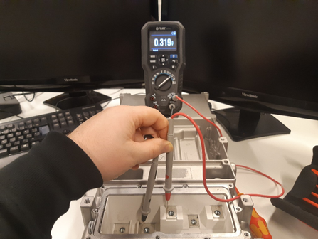
Figure 2. Diode measurement from L1 to DC+.
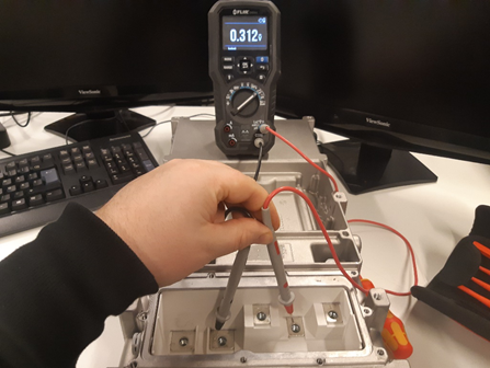
Figure 3. Diode measurement from L2 to DC+.
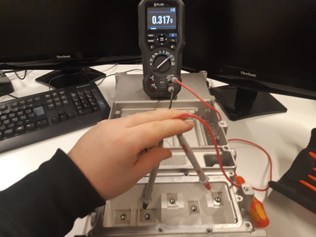
Figure 4. Diode measurement from L3 to DC+.
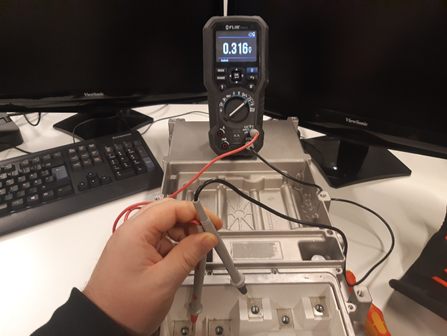
Figure 5. Diode measurement from DC- to L1.
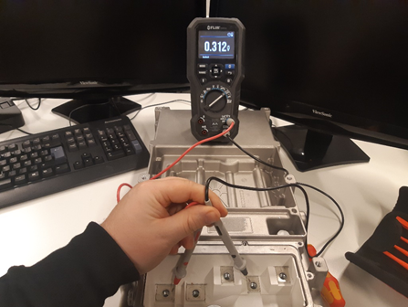
Figure 6. Diode measurement from DC- to L2.
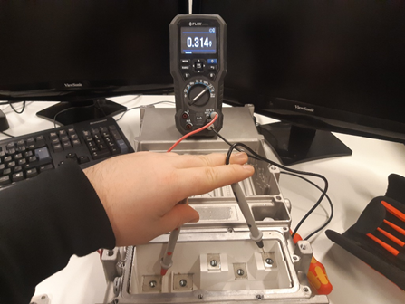
Figure 7. Diode measurement from DC- to L3.
You can double check the condition of diodes by changing the order of the probes (switch between plus and minus), so that you will measure the reverse biased diode threshold. The multimeter should indicate open loop (OL) if diodes are intact.