This article describes measures to avoid EMC issues in Danfoss Editron systems or other systems with Editron devices installed. Besides the Editron devices and systems, the customer or installer must also consider all other installed devices and systems and define an EMC plan according to the whole system layout and specifications. Regular rules for common installation practice, like avoiding sharp edges on cable routes etc. is not covered in this guide.
In general, only screened copper cables are to be used for Danfoss Editron systems. Allowed manufacturers and cable types are mentioned in the electric drawings of the specific project in case of a Danfoss system, or in the user manuals of the devices for individual device purchases.
Please contact Danfoss Editron when these instructions conflict equipment supplier installation information.
Cable installation
Danfoss Editron systems utilize single core power cables to/from the EC-C inverters and other devices. These have a surrounding magnetic field which must be carefully managed. The magnetic field can cause heat development of surrounding ferrous or conductive materials (via eddy currents) when no precautions are taken.
Therefore, installer must take special care when installing single core power cables; only non-ferromagnetic cable ties, EMC-type cable glands and non-ferromagnetic cabinet plates must be used.
The magnetic field of the cables are minimized when the power cables are mounted symmetrically against each other (without mixing cables from equipment in different subsystems).
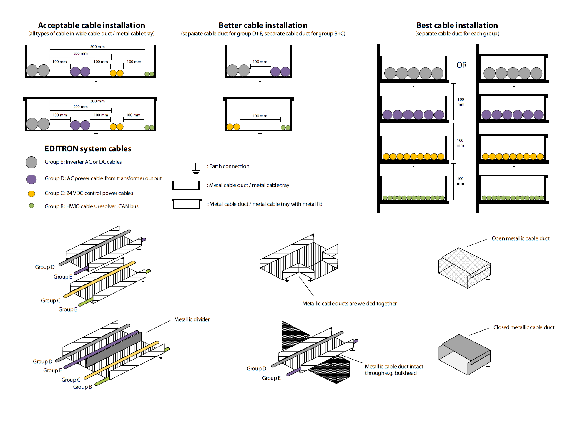
Danfoss Editron categorizes cables according to cable segregation groups as shown in table below.
| Criteria | Signal level | Group | Example devices | |
| LF/DC | Application | |||
| Very sensitive | 1 mV | 1 µV | A |
Receiver/TV antenna cables Radio/radar MF receiver cables Dynamic microphone input |
| Sensitive | 100 mV | 10 µV | B |
Resolver/encoder cables HW I/O cables to PLC HW I/O cables to inverter Bus and communication cables (CAN bus, Modbus, Ethernet, etc.) |
|
Low sensitivity, low interference |
24 V | 10 µV | C |
Power supply cables Telephone and loudspeaker cables 24 VDC control power cables |
| Interference | 440 V | 3 V | D |
Clean AC power cables e.g. microgrid inverter output cables after filter/transformer 230 VAC control power cables Cables for AC heating |
| High interference | 440 V | 30 V | E |
DC power cables between inverter and DC switchboard AC power cables between inverter and machine (motor cables) AC power cables between inverter, LC filter and/or transformer |
| High sensitivity with high interference | 1000 V | 1000 V | F | High-power radio transmit and receiver cables |
| Immune, no interference | Z | Fiber optic cables | ||
Cable segregation minimal distances in millimeters are shown in table below.
| Group |
A | B | C | D | E | F |
| A | - | 100 | 200 | 300 | 400 | 400 |
| B | 100 | - | 100 | 200 | 300 | 400 |
| C | 200 | 100 | - | 100 | 200 | 300 |
| D | 300 | 200 | 100 | - | 100 | 200 |
| E | 400 | 300 | 200 | 100 | - | 400 |
| F | 400 | 400 | 300 | 200 | 400 | - |
Cable crossings between different cable groups are to be avoided wherever possible, and if required the crossing must be perpendicular (at an angle of 90°). See figure below for an example.

It is not recommended to cross cables of groups B and E in close proximity, instead the described installation distance should be enforced even when the cables cross perpendicularly. Installation of all cables should be done according to the instructions regarding the grouping A-F as described in the picture below.
Low-voltage cabling
It is strongly recommended that all low-voltage signal cables connected to Danfoss devices are screened. Twisted pair cables should be used in cases of differential communication signals such as CAN bus, resolver, and synchronization cabling. Twisted pair signal cable is also recommended for PT100 or PT1000 temperature sensors, I/O cabling and other similar low-voltage connections to reduce interference and improve the EMC of the system.
Cable cross-sectional area is dictated by the maximum current of the cable and required signal strength. Auxiliary power feed (24 V power) should always be protected with a suitable low-voltage DC fuse. Fuse amperage rating should be selected according to the installation, so that all safety and protection requirements are met.
Ideally, the auxiliary power for Danfoss Editron devices should be galvanically isolated from the system/vehicle/vessel chassis and other large conductive structures. If the low-voltage power feed is connected to a grounding structure, for example a 24 V battery with the minus terminal connected to vehicle chassis, it is recommended to use a 24/24 V isolator/power supply or similar to reduce interference and prevent ground loops and other potential issues.
Power cable length, screening and filtering
To comply with the EMC directives category C2 and C3 on product level, the Danfoss EC-C1200-450 inverter AC power cables must be shielded, and less than 15 m long (e.g. between inverter and machine). For AC power cables >15 m a du/dt filter is required. See table below for an overview.
|
Drive Type/Rating |
EMC Category |
||
|
3 phase, 500VAC input |
Category C1 |
Category C2 |
Category C3 |
|
External filter required |
External filter required |
No additional filtering required |
|
|
Shielded motor cables always required |
|||
|
If the cable length is over 15m, an output du/dt filter must be used for shielded motor cables. Contact Danfoss Editron representative to select the right du/dt filter. |
|||
In all cases all cable screens need to be connected to system ground potential on both cable ends, and the cable screen must have a 360° connection for proper high frequency performance. Cable screens are not intended for grounding but to restrict noise from exiting and entering system(s). Please read the electrical installation instructions of the Danfoss Editron EM machines, EC-LTS external inductance units, and EC-C inverters for proper cable screen mounting.
Grounding requirements
In case a common frame is hard to establish, a bonding connection between all electrical equipment in the subsystem must be utilized to equalize potentials in the installation. Wherever installation wise possible, the bonding should be made with flat bonding braids. In case it is challenging to use flat bonding braids, the sizing of a round bonding cable between the components must be chosen according to table below.
|
Bonding cable size / Largest power cable size |
25 mm2 |
35 mm2 |
50 mm2 |
70 mm2 |
95 mm2 |
120 mm2 |
150 mm2 |
185 mm2 |
|
35 mm2 |
<5m |
<10m |
<15m |
<20m |
<25m |
<30m |
<35m |
<40m |
|
50 mm2 |
- |
<5m |
<10m |
<15m |
<20m |
<25m |
<30m |
<35m |
|
2ll 35 mm2 |
- |
- |
<5m |
<10m |
<15m |
<20m |
<25m |
<30m |
|
70 mm2 |
- |
- |
<5m |
<10m |
<15m |
<20m |
<25m |
<30m |
|
95 mm2 |
- |
- |
- |
<5m |
<10m |
<15m |
<20m |
<25m |
|
2 ll 50 mm2 |
- |
- |
- |
<5m |
<10m |
<15m |
<20m |
<25m |
|
2 ll 70 mm2 |
- |
- |
- |
- |
<5m |
<10m |
<15m |
<20m |
|
2 ll 95 mm2 |
- |
- |
- |
- |
- |
<5m |
<10m |
<15m |
Largest power cable size means the largest of the inverter DC power cables or the AC power cables, whichever is bigger.
Connection of Danfoss Editron equipment to the structure of the system/vehicle/vessel with bonding braids should be kept as short as possible for realizing a low impedance connection also at high frequencies (inverter switching frequency of 8 kHz). For more details on grounding of Danfoss devices, see article General grounding (earthing) guidelines of Danfoss devices.